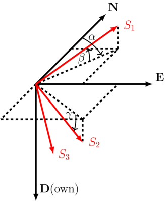
Geographical coordinate system
\[
\mathbf{R}_G = \begin{bmatrix}
\cos\alpha \cos\beta & \sin\alpha \cos\beta & -\sin\beta \\
\cos\alpha \sin\beta\sin\gamma - \sin\alpha\cos\gamma & \sin\alpha\sin\beta\sin\gamma + \cos\alpha\cos\gamma & \cos\beta\sin\gamma \\
\cos\alpha\sin\beta\cos\gamma + \sin\alpha\sin\gamma & \sin\alpha\sin\beta\cos\gamma - \cos\alpha\sin\gamma & \cos\beta\cos\gamma
\end{bmatrix}
\]
Stress in geographical coordinate system
\[
\mathbf{S}_G = \mathbf{R}_G^T \mathbf{S} \mathbf{R}_G
\]
Example: Strike-slip faulting
|
\[\mathbf{S}=\begin{bmatrix} 30 & 0 & 0 \\ 0 & 25 & 0 \\ 0 & 0 & 20 \end{bmatrix}\]
|
\[\quad\quad\quad\]
|
\[\begin{align} \alpha &= 0^{\circ} & \mbox{Azimuth of } S_{Hmax} \\ \beta &= 0^{\circ} & S_1 = S_{Hmax} \\ \gamma &= 90^{\circ} & S_2 = S_v \end{align}\]
|
\[
\mathbf{R}_G = \begin{bmatrix} 1 & 0 & 0 \\ 0 & 0 & 1 \\ 0 & -1 & 0 \end{bmatrix}
\]
\[
\mathbf{S}_G = \begin{bmatrix} 30 & 0 & 0 \\ 0 & 20 & 0 \\ 0 & 0 & 25 \end{bmatrix}
\]
Example: Normal faulting
|
\[\mathbf{S} = \begin{bmatrix} 30 & 0 & 0 \\ 0 & 25 & 0 \\ 0 & 0 & 20 \end{bmatrix}\]
|
\[\quad\quad\quad\]
|
\[\begin{align} \alpha &= 0^{\circ} & \mbox{Azimuth of } S_{hmin} \\ \beta &= -90^{\circ} & S_1 = S_v \\ \gamma &= 0^{\circ} & \end{align}\]
|
\[
\mathbf{R}_G = \begin{bmatrix} 0 & 0 & 1 \\ 0 & 1 & 0 \\ -1 & 0 & 0 \end{bmatrix}
\]
\[
\mathbf{S}_G = \begin{bmatrix} 20 & 0 & 0 \\ 0 & 25 & 0 \\ 0 & 0 & 30 \end{bmatrix}
\]
Example: Reverse faulting
|
\[\mathbf{S} = \begin{bmatrix} 30 & 0 & 0 \\ 0 & 25 & 0 \\ 0 & 0 & 20 \end{bmatrix}\]
|
\[\quad\quad\quad\]
|
\[\begin{align} \alpha &= 90^{\circ} & \mbox{Azimuth of } S_{Hmax} \\ \beta &= 0^{\circ} & S_1 = S_{Hmax} \\ \gamma &= 0^{\circ} & S_2 = S_{hmin} \end{align}\]
|
\[
\mathbf{R}_G = \begin{bmatrix} 0 & 1 & 0 \\ -1 & 0 & 0 \\ 0 & 0 & 1 \end{bmatrix}
\]
\[
\mathbf{S}_G = \begin{bmatrix} 25 & 0 & 0 \\ 0 & 30 & 0 \\ 0 & 0 & 20 \end{bmatrix}
\]
Example: Strike-slip faulting
|
\[\mathbf{S} = \begin{bmatrix} 60 & 0 & 0 \\ 0 & 40 & 0 \\ 0 & 0 & 35 \end{bmatrix}\]
|
\[\quad\quad\quad\]
|
\[\begin{align} \alpha &= 135^{\circ} & \mbox{Azimuth of } S_{Hmax} \\ \beta &= 0^{\circ} & S_1 = S_{Hmax} \\ \gamma &= 90^{\circ} & S_2 = S_{v} \end{align}\]
|
\[
\mathbf{R}_G = \begin{bmatrix} -\frac{1}{\sqrt{2}} & \frac{1}{\sqrt{2}} & 0 \\ 0 & 0 & 1 \\ \frac{1}{\sqrt{2}} & \frac{1}{\sqrt{2}} & 0 \end{bmatrix}
\]
\[
\mathbf{S}_G = \begin{bmatrix} 47.5 & -12.5 & 0 \\ -12.5 & 47.5 & 0 \\ 0 & 0 & 40 \end{bmatrix}
\]
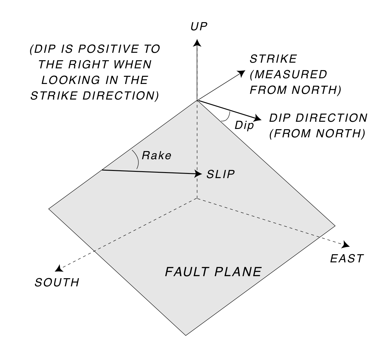
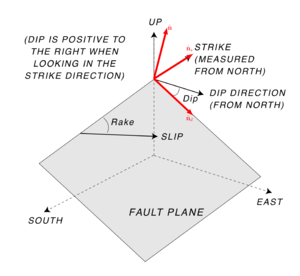
Fault traction and stress
Traction on fault plane
\[\begin{equation}
\vec{t} = \mathbf{S}_G \cdot \hat{\mathbf{n}}
\end{equation}\]
Normal stress to plane
\[\begin{equation}
S_n = \vec{t}^\intercal \cdot \hat{\mathbf{n}}
\end{equation}\]
Shear stress in dip direction
\[\begin{equation}
\tau_d = \vec{t}^\intercal \cdot \hat{\mathbf{n}}_d
\end{equation}\]
Shear stress in strike direction
\[\begin{equation}
\tau_s = \vec{t}^\intercal \cdot \hat{\mathbf{n}}_s
\end{equation}\]
Example: Strike-slip faulting
|
\[\mathbf{S}_G = \begin{bmatrix} 30 & -8.66 & 0 \\ -8.66 & 40 & 0 \\ 0 & 0 & 30 \end{bmatrix}\]
|
\[\quad\quad\quad\]
|
\[\begin{align} strike &= 60^{\circ} \\ dip &= 90^{\circ} \end{align}\]
|
|
\[\quad\hat{\mathbf{n}} = \begin{bmatrix} -0.866 \\ 0.5 \\ 0 \end{bmatrix}\quad\]
|
\[\quad\hat{\mathbf{n}}_s = \begin{bmatrix} 0.5 \\ 0.866 \\ 0 \end{bmatrix}\quad\]
|
\[\quad\hat{\mathbf{n}}_d = \begin{bmatrix} 0 \\ 0 \\ 1.0 \end{bmatrix}\quad\]
|
\[S_n = 40 \quad \tau_d = 0 \quad \tau_s = 8.66\]
Example: Normal faulting
|
\[\mathbf{S}_G = \begin{bmatrix} 4000 & 0 & 0 \\ 0 & 3000 & 0 \\ 0 & 0 & 5000 \end{bmatrix}\]
|
\[\quad\quad\quad\]
|
\[\begin{align} strike &= 45^{\circ} \\ dip &= 60^{\circ} \end{align}\]
|
|
\[\quad\hat{\mathbf{n}} = \begin{bmatrix} -0.612 \\ 0.612 \\ -0.5 \end{bmatrix}\quad\]
|
\[\quad\hat{\mathbf{n}}_s = \begin{bmatrix} 0.707 \\ 0.707 \\ 0 \end{bmatrix}\quad\]
|
\[\quad\hat{\mathbf{n}}_d = \begin{bmatrix} -0.3535 \\ 0.3535 \\ 0.866 \end{bmatrix}\quad\]
|
\[S_n = 3875 \quad \tau_d = -650 \quad \tau_s = -433\]
Example: Normal faulting
|
\[\mathbf{S}_G = \begin{bmatrix} 5000 & 0 & 0 \\ 0 & 4000 & 0 \\ 0 & 0 & 3000 \end{bmatrix}\]
|
\[\quad\quad\quad\]
|
\[\begin{align} strike &= 225^{\circ} \\ dip &= 60^{\circ} \end{align}\]
|
|
\[\quad\hat{\mathbf{n}} = \begin{bmatrix} 0.612 \\ -0.612 \\ -0.5 \end{bmatrix}\quad\]
|
\[\quad\hat{\mathbf{n}}_s = \begin{bmatrix} -0.707 \\ -0.707 \\ 0 \end{bmatrix}\quad\]
|
\[\quad\hat{\mathbf{n}}_d = \begin{bmatrix} 0.3535 \\ -0.3535 \\ 0.866 \end{bmatrix}\quad\]
|
\[S_n = 4125 \quad \tau_d = -650 \quad \tau_s = -433\]
Example: Revese faulting
|
\[\mathbf{S}_G = \begin{bmatrix} 2100 & -520 & 0 \\ -520 & 1500 & 0 \\ 0 & 0 & 1000 \end{bmatrix}\]
|
\[\quad\quad\quad\]
|
\[\begin{align} strike &= 120^{\circ} \\ dip &= 70^{\circ} \end{align}\]
|
|
\[\quad\hat{\mathbf{n}} = \begin{bmatrix} -0.814 \\ -0.470 \\ -0.342 \end{bmatrix}\quad\]
|
\[\quad\hat{\mathbf{n}}_s = \begin{bmatrix} -0.5 \\ 0.866 \\ 0 \end{bmatrix}\quad\]
|
\[\quad\hat{\mathbf{n}}_d = \begin{bmatrix} 0.2961 \\ -0.1710 \\ 0.9396 \end{bmatrix}\quad\]
|
\[S_n = 1441 \quad \tau_d = 161 \quad \tau_s = 488\]
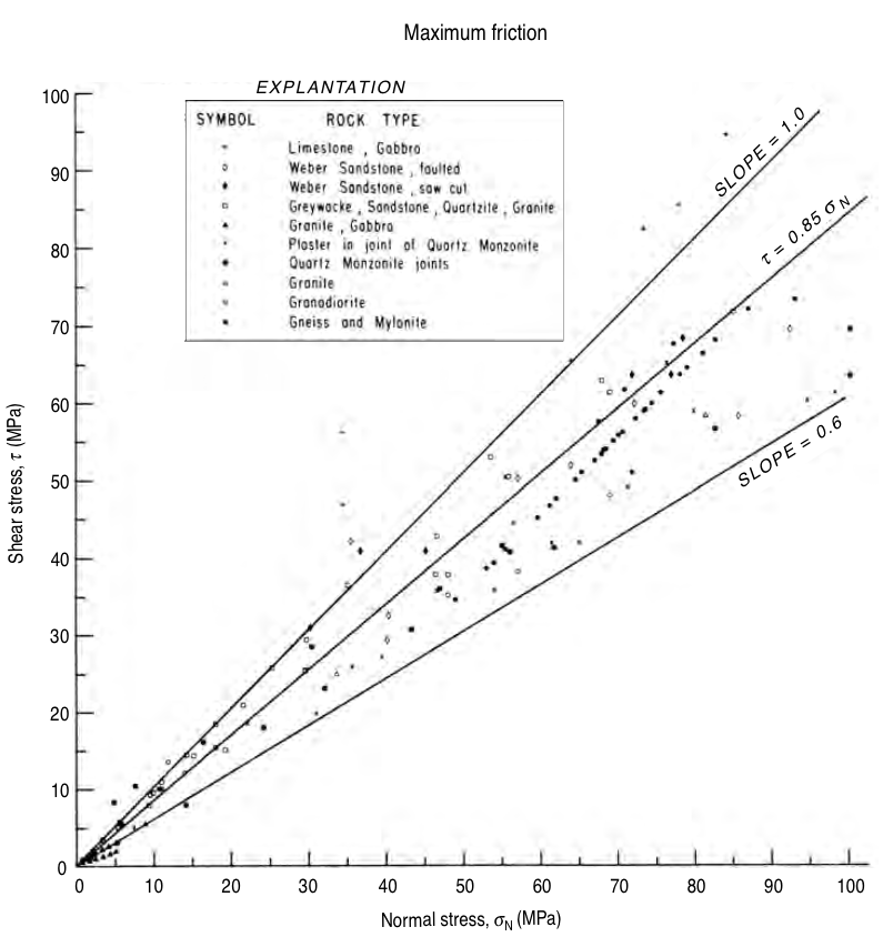
Shear failure (slip on faults)
\[
\dfrac{\tau}{\sigma_n} = \mu
\]
Coulomb failure function
\[
f = \tau - \mu \sigma_n \le 0
\]
Induced seismicity

|
|
Fluid injection and seismicity at the Rocky Mountain Arsenal
|
© Cambridge University Press Zoback, Reservoir Geomechanics (Fig. 4.22a, pp. 125)