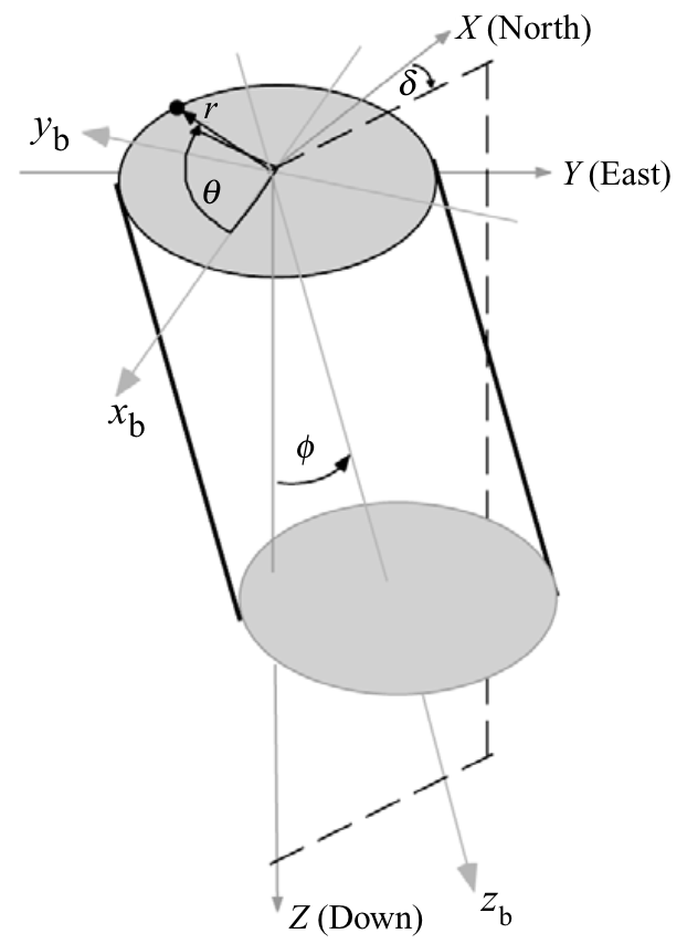
Stresses in the wellbore coordinate system
\[
\mathbf{R}_B = \begin{bmatrix}
\cos\delta \cos\phi & \sin\delta \cos\phi & -\sin\phi \\
-\sin\delta & \cos\delta & 0 \\
\cos\delta\sin\phi & \sin\delta\sin\phi & \cos\phi
\end{bmatrix}
\]
\[
\mathbf{S}_B = \mathbf{R}_B \mathbf{S}_G \mathbf{R}_B^T
\]
\[
\mathbf{S}_B = \mathbf{R}_B (\mathbf{R}_G^T \mathbf{S} \mathbf{R}_G) \mathbf{R}_B^T
\]
Stress at wellbore wall
\[\begin{align}
\sigma_{zz} &= \sigma_{33} - 2 \nu (\sigma_{11} - \sigma_{22})\cos 2\theta - 4 \nu \sigma_{12} \sin 2 \theta \\
\sigma_{\theta\theta} &= \sigma_{11} + \sigma_{22} - 2(\sigma_{11} - \sigma_{22})\cos 2\theta - 4 \sigma_{12} \sin 2\theta - \Delta P \\
\tau_{\theta z} &= 2 (\sigma_{23} \cos \theta - \sigma_{13} \sin \theta) \\
\sigma_{rr} &= \Delta P
\end{align}\]
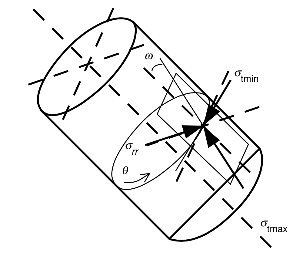
Principal effective stresses around the wellbore
![]()
|
\(\quad\quad\)\[\begin{align}\sigma_{t\mbox{max}} &=\frac{1}{2}\left(\sigma_{zz} + \sigma_{\theta\theta} + \sqrt{(\sigma_{zz} - \sigma_{\theta\theta})^2 + 4 \tau_{\theta z}^2}\right) \\
\sigma_{t\mbox{min}} &=\frac{1}{2}\left(\sigma_{zz} + \sigma_{\theta\theta} - \sqrt{(\sigma_{zz} - \sigma_{\theta\theta})^2 + 4 \tau_{\theta z}^2}\right)
\end{align}\]
|
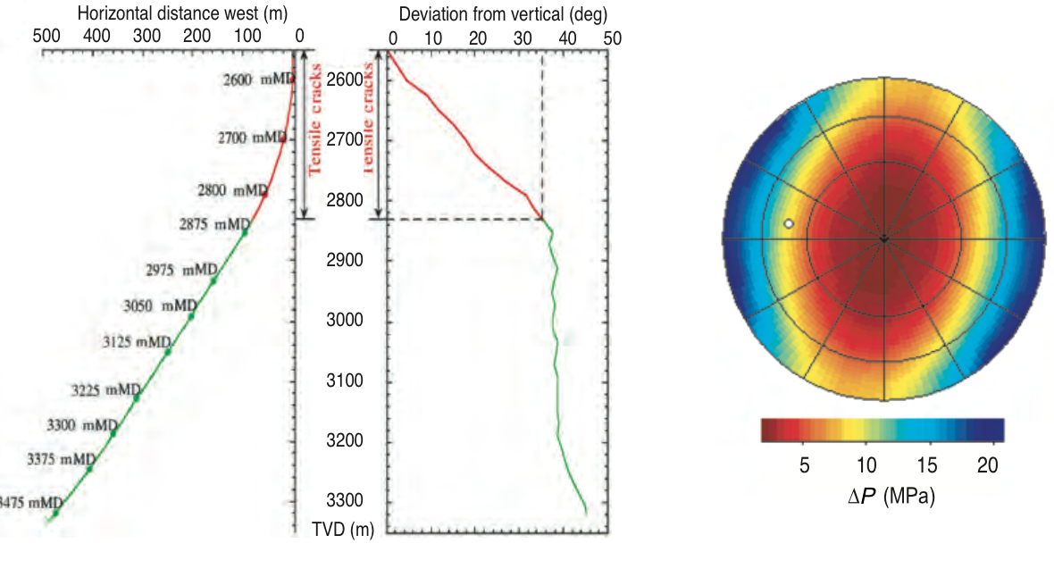
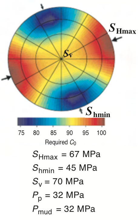
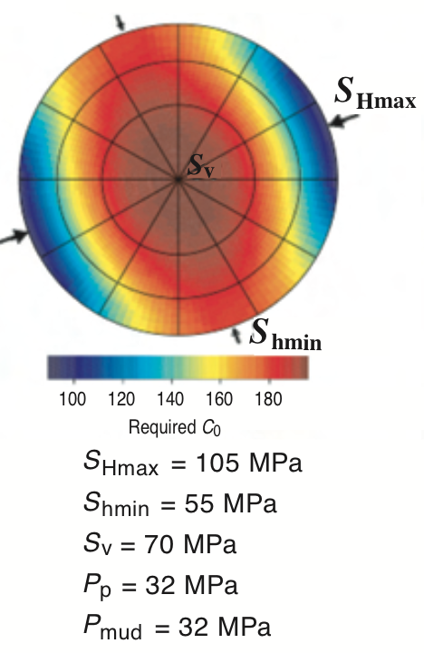
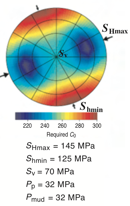
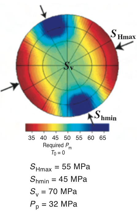
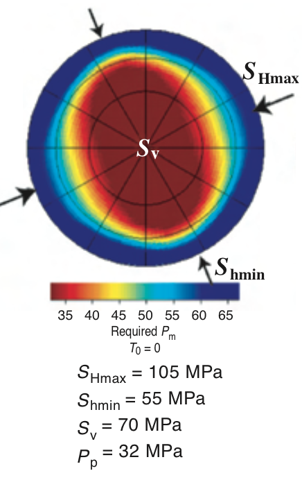
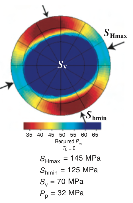
Example
![]()